AI-translated. Read the original in KoreanEmbedded slides, videos and images remain in their original language.
Voice-Controlled Air Conditioning with Amazon Echo

Designing an air-conditioner control circuit and using LIRC
This post aims to be accessible even to readers with little hardware experience.
Do you remember the siren and radio kits sold at stationery shops when you were in elementary school? After enjoying a science lesson about making a simple light-bulb circuit, I bought a siren kit. Unfortunately, I didn’t know that soldering required solder. I bought only a soldering iron, tried to use it, and failed miserably. It was another ten years before I actually soldered anything, in an undergraduate digital logic design class. These days, I build a lock-screen advertising platform in Python, a high-level language, but part of me has always wanted to work with hardware.
For this project, I wanted to make something useful for the company. That led me to the idea of controlling our air conditioners by voice. One floor of Buzzvil’s office has three air conditioners. In summer, someone has to turn all three on individually. Worse, two are Samsung units and one is LG, so we need two remotes. Wouldn’t people appreciate turning them all on at once—and wouldn’t voice control be cool? With devices such as the Raspberry Pi and Amazon Echo, it’s now possible to build this relatively inexpensively. I set the following goal: say something like
- “Alexa, turn on the AC”
- “Alexa, could you please turn off the AC?”
and have the system turn the air conditioners on or off. We use Slack at work, and it supports custom commands, so I also wanted Slack controls:
/acon— turn the air conditioner off/acoff— turn the air conditioner on/acwarm— gentler cooling/acmedium— medium cooling/accool— stronger cooling
Controlling an air conditioner directly might sound difficult, but there is a surprisingly simple approach: imitate its remote control. Remotes communicate with devices using infrared light. Look at the front of a remote, and you’ll see a small protruding LED. It sends infrared signals by blinking in particular patterns. A visible-light LED could presumably do the same job, but nobody would enjoy a flash every time they pressed a button. Once we know an infrared LED can control the AC, we can sketch the overall system.
The first step is a circuit diagram. To imitate a remote, we need to analyze the signal emitted when a button is pressed. That requires an infrared receiver, so our circuit has two parts: a transmitter and a receiver.
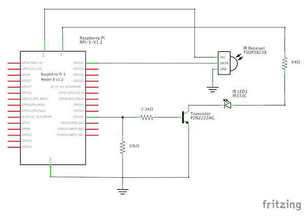
I chose a TSOP38238 infrared receiver. Its power pins connect to 3 V (+) and ground (−), and its output connects to a Raspberry Pi GPIO pin. GPIO stands for General Purpose Input/Output. These pins use voltage levels to send outputs or read external signals. Each pin is configured for either input or output. GPIO is digital, so it recognizes only 0 and 1. Raspberry Pi GPIO uses 3.3 V: 0 V represents 0 and 3.3 V represents 1. You can check which pins are available at pinout.xyz.
You can choose whichever available GPIO pins suit your needs. Pins close to ground and the 3.3 V or 5 V power pins make wiring easier. Another tip is to avoid pins with special functions where possible. Serial communication features, for example, are available only on particular pins. Later, when I tried to add a light sensor, I found that it needed a pin I was already using and had to move my wiring.
For the infrared transmitter, I chose an IR333C. The transmitter circuit resembles a light-bulb circuit with a switch. The differences are a 68-ohm series resistor to limit current through the LED and a transistor in place of a physical switch. A transistor lets us allow or block current electronically. Connecting its base to a Raspberry Pi GPIO pin lets us turn the LED on and off. You might wonder why we don’t connect the LED directly to the GPIO’s 3.3 V output. GPIO is intended for signaling and cannot supply the power this LED needs. We therefore power the LED from a dedicated power pin and use the transistor to switch it.
Two resistors remain unexplained: a 2.2-kilohm base resistor and a 10-kilohm pull-down resistor. Explaining exactly why they are needed and how to choose their values is beyond my expertise; writing this post sent me back to study them again. Broadly, they protect the circuit and keep it operating reliably. Search for “LED,” “BJT,” “MOSFET,” “base resistor,” “gate resistor,” and “pull-down resistor” for more information. The reasons differ depending on whether the transistor is a MOSFET or a BJT, so make sure your reference matches the type you are using.
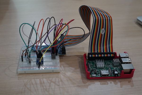
I built a breadboard prototype from the diagram. You need to buy the breadboard separately. Searching for a Raspberry Pi input/output kit will turn up bundles containing a breadboard, connectors, jumper wires, and assorted resistors for around KRW 15,000. It’s a convenient option if you don’t want to research each part individually.
Infrared LEDs have different emission angles. The narrower the angle, the more accurately you need to point the LED at the air conditioner. The IR333C has a 40-degree angle. Since our air conditioners are ceiling-mounted, I planned to place the finished circuit on a desk underneath. But it wouldn’t be fixed in place, so someone could bump it and stop it from working. A wider-angle LED would make it more reliable. I searched DigiKey, a useful electronic components site, with these filters:
Type = IR
Wavelength = 940nm
Viewing Angle >= 80 degrees
Mounting Type = Through Hole
That led me to the SLED-56-16639, which has a 140-degree viewing angle. A Korean supplier carried it, too. It was much more expensive than the IR333C, so I bought just one to try.
With the circuit built, the next step was configuring the Raspberry Pi to control it. Fortunately, Linux has LIRC—Linux Infrared Remote Control—which makes infrared applications much easier to build. Install it with:
sudo apt-get install lirc
This installs tools such as mode2, irsend, and irrecord, along with the lircd daemon. The daemon lets programs send and receive infrared signals through Unix domain sockets. Your application only needs to communicate with the socket; lircd handles the rest. After installation, configure the pins by editing these files:
/boot/config.txt
dtoverlay=lirc-rpi,gpio\_in\_pin=23,gpio\_out\_pin=21
/etc/modules
lirc_dev
lirc_rpi gpio_in_pin=23 gpio_out_pin=21
/etc/lirc/hardware.conf
LIRCD_ARGS="--uinput"
DRIVER="default"
DEVICE="/dev/lirc0"
MODULES="lirc_rpi"
Restart the Raspberry Pi after editing the files. I used irrecord to capture infrared signals:
irrecord -d /dev/lirc0 lircd.conf
Run this command, then press the remote buttons you want to capture. The infrared receiver records the results in lircd.conf. The process has two main stages. First, it identifies the protocol. Infrared signals encode information as blinking patterns, and different protocols can express the same information differently. To work out the protocol, irrecord asks you to press various buttons repeatedly. After several dozen presses, it moves to the second stage: recording individual buttons. Enter a button name and press that button on the remote. The protocol specification and button packet values are written to lircd.conf, in this format:
begin remote

  name  lg-ac
  bits           20
  flags SPACE_ENC|CONST_LENGTH
  eps            30
  aeps          100

  header       3204  9803
  one           575  1497
  zero          575   462
  ptrail        575
  pre_data_bits   8
  pre_data       0x88
  gap          106773
  toggle_bit_mask 0x0

      begin codes
          BTN_0                    0xC0051 0xFF312 # 끄기

          BTN_1                    0x00314 0xFF345 # 냉방/18도/1바람
          BTN_2                    0x00303 0xFF345 # 냉방/18도/2바람
          BTN_3                    0x00347 0xFF345 # 냉방/18도/4바람
      end codes

end remote
The first section contains protocol settings such as flags, header, and gap. The entries named BTN_0, BTN_1, and so on are the captured button packets. Studying infrared protocols wasn’t the goal of this project, so I kept the settings generated by irrecord and focused on analyzing the packet values.
There is one especially important property of these remotes: communication is one-way. The remote can send information to the AC, but it cannot receive information back. When you press the power-on button, the LCD shows a temperature stored in the remote itself, not a value retrieved from the AC. This creates the possibility of the remote and AC disagreeing. Imagine pressing temperature-up three times while out of range, then once after returning within range. If the remote sent only “increase temperature,” its displayed temperature and the AC’s setting could differ by three degrees.
To avoid that problem, the protocol sends the desired state—the temperature to set—rather than just the action of increasing it. It sends the temperature not only when a temperature button is pressed but also when power-on is pressed, so the two devices agree when the unit starts. We can therefore expect the packet to contain something like “pressed button code” plus “all AC settings: temperature, fan speed, airflow direction, and so on.” Here is what I captured from the LG remote:
begin codes
    BTN_0                    0xC0051 0xFF312 # 끄기

    BTN_1                    0x00314 0xFF345 # 냉방/18도/1바람
    BTN_2                    0x00303 0xFF345 # 냉방/18도/2바람
    BTN_3                    0x00347 0xFF345 # 냉방/18도/4바람

    BTN_4                    0x00617 0xFF345 # 냉방/21도/1바람
    BTN_5                    0x00606 0xFF345 # 냉방/21도/2바람
    BTN_6                    0x0064A 0xFF345 # 냉방/21도/4바람

    BTN_7                    0x0091A 0xFF345 # 냉방/24도/1바람
    BTN_8                    0x00909 0xFF345 # 냉방/24도/2바람
    BTN_9                    0x0094D 0xFF345 # 냉방/24도/4바람

    BTN_10                   0x00C1D 0xFF345 # 냉방/27도/1바람
    BTN_11                   0x00C0C 0xFF345 # 냉방/27도/2바람
    BTN_12                   0x00C50 0xFF345 # 냉방/27도/4바람

    BTN_50                   0x04B10 0xFF345 # 난방/26도/1바람
    BTN_51                   0x04B0F 0xFF345 # 난방/26도/2바람
    BTN_52                   0x04B43 0xFF345 # 난방/26도/4바람

    BTN_53                   0x04D12 0xFF345 # 난방/28도/1바람
    BTN_54                   0x04D01 0xFF345 # 난방/28도/2바람
    BTN_55                   0x04D45 0xFF345 # 난방/28도/4바람

    BTN_56                   0x04F14 0xFF345 # 난방/30도/1바람
    BTN_57                   0x04F03 0xFF345 # 난방/30도/2바람
    BTN_58                   0x04F47 0xFF345 # 난방/30도/4바람
end codes
I used only two buttons: off and on. Since the on button always transmits the temperature state, it can also be used to adjust the temperature. The packet consists of ten hexadecimal digits: the left five represent the AC state, and the right five identify the button. Off is 0xFF312; on is 0xFF345. Adding 0x00303 to the state value on the left raises the temperature by three degrees. After a few captures, the pattern lets you infer other values without recording every combination. That made the LG remote straightforward.
The Samsung remote was another story. Every attempt with irrecord failed with an error. I suspected a nonstandard protocol, and reports of checksum logic suggested that analyzing it wouldn’t be easy. Still, however complicated the protocol, it ultimately becomes a blinking LED. If we could capture the raw waveform and replay it, we wouldn’t need to decode it. Fortunately, the mode2 utility can output a received raw waveform in a form usable in lircd.conf:
sudo mode2 -m -d /dev/lirc0 > lirc.conf
Here is the resulting Samsung configuration. The file is large, so I’ve included only the beginning:
begin remote

  name  samsung-ac
  flags RAW_CODES
  eps            30
  aeps          100

  gap          8929

      begin raw_codes

          name BTN_0
              632    17684     3048     8887      541      444
              552     1440      545      441      556      436
              547      444      550      441      552      439
              554      439      556      435      550     1438
              551      440      554      436      557     1455
              535     1452      545      443      551     1435
              552     1429      548     1437      551     1432
              556     1427      550      441      553      439
              555      437      558      434      549      443
              551      467      527      465      529      463
              542      450      544      448      553      440
              547      444      550      442      553      439
              554      438      556      436      548      444
              549      443      552      440      554      438
              556      436      549      443      550      442
              552      440      554      464      530      462
...
Unlike the LG configuration, it takes a lot of information to define a single button. Placing both configurations in /etc/lirc/lircd.conf lets the daemon load and register the commands when it starts. I named the devices lg-ac and samsung-ac. Managing both in one file was inconvenient, so I replaced the file contents with:
include "conf.d/samsung-ac.conf"
include "conf.d/lg-ac.conf"
I created the conf.d directory and put each model’s definition in its own file. This worked as intended. I had wanted to use a glob such as include "conf.d/*", but it didn’t work for some reason, so I listed the files explicitly. We can now control the infrared transmitter with irsend:
irsend SEND_ONCE lg-ac BTN_1
irsend SEND_ONCE samsung-ac BTN_2
At this point, I could control the air conditioners from the Raspberry Pi shell. For anyone curious, here is the parts bill:
- Raspberry Pi 3, official case, and heat sink: KRW 53,350
- SD card: KRW 4,410
- Transistor: KRW 700
- Infrared LED: KRW 400
- Resistors: KRW 100
- Prototype board: KRW 1,300
- Board supports: KRW 100
- Jumper wires: KRW 300
- Total: KRW 60,660
The Raspberry Pi Zero W was released earlier this year. It removes some features from the Pi 3 to bring the price down to USD 10 overseas, although Korean retailers were selling more expensive bundles. It has everything this project needs, so I plan to try one when I get the chance.
Prototype boards come in several materials. The cheapest, paper phenolic, didn’t look great, so I bought a sturdier, better-looking epoxy board. The yellow-brown boards are phenolic; the green ones are epoxy. Resistor size varies with power rating. Half-watt resistors are rather large; quarter-watt parts are a reasonable general choice. Eighth-watt parts would also work here, since current flows only during the LED’s brief flashes.
Here is what I spent on soldering equipment and supplies:
- Raspberry Pi input/output kit: KRW 14,600
- AWG30 Teflon wire: KRW 5,380
- Kester 1.0 mm leaded solder, 50 g: KRW 4,400
- FLUKE-101 multimeter: KRW 43,500
- HAKKO FX-888D digital soldering station: KRW 143,550
- T18-K replacement tip: KRW 11,880
- Cutters and tweezers: already owned
- Total: KRW 223,310
I spent quite a lot on equipment. If you avoid impulsively buying an expensive soldering station and multimeter as I did, you can get started for much less. I do recommend buying a multimeter so you can quickly diagnose a circuit that doesn’t work. If a premium Fluke model is too expensive, I’ve heard that the VC99 offers good value.
That covers the circuit design and LIRC setup for controlling our air conditioners. Details of the server network, Amazon Echo and Slack integrations, deployment, and automated testing are available in the GitHub repository. Thanks for reading!